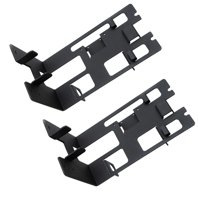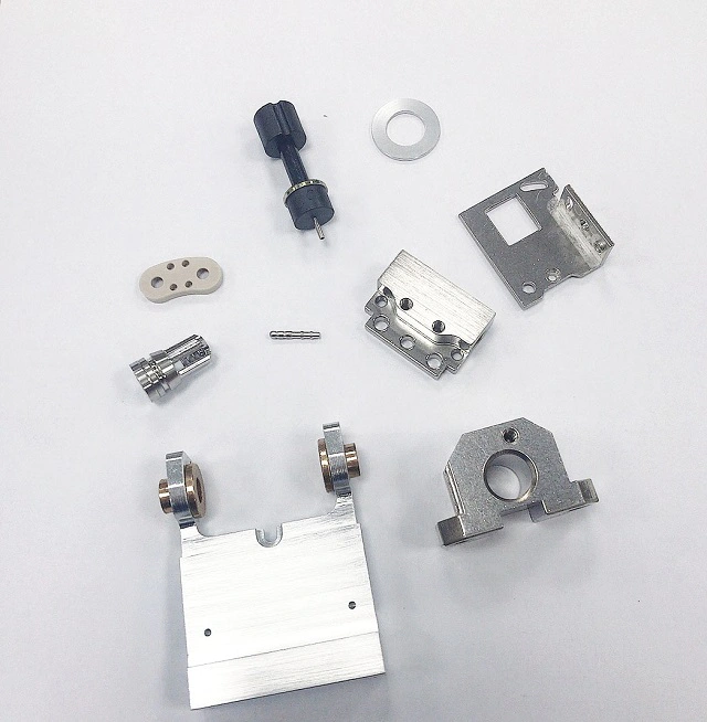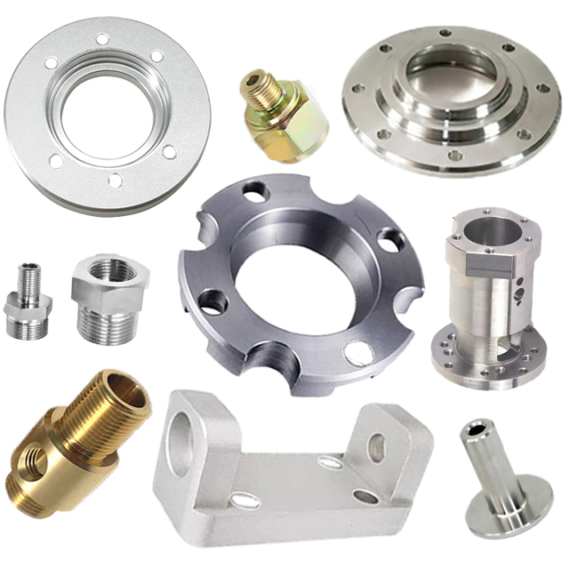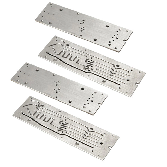

Discover the precision world of CNC machine parts: quality and endless possibilities
The machining factory shares with you the method of realizing spiral processing on ordinary wire cutting machine tools
by:Jingte
2022-07-26
The machining factory shares with you the method of realizing spiral processing on ordinary wire cutting machine tools
The machining factory shares with you the method of realizing spiral processing on ordinary wire cutting machine tools
The ordinary wire cutting machine tool in the machining plant is a typical two-axis linkage type CNC machine tool. Generally, it can only be used for cutting various two-dimensional graphics, and its processing technology range is relatively narrow. How to broaden the processing technology range of ordinary wire cutting machine tools so that it can better meet the objective production needs has always been a concern of the majority of wire cutting users. Based on years of practical work experience in machining factories, this paper specifically introduces the method of realizing helical machining on ordinary wire cutting machine tools.
Realization of Spiral Motion
Spiral motion is composed of two basic motions, linear motion and rotational motion. To realize helical machining on an ordinary wire-cutting machine tool, in addition to using one axis (X-axis or Y-axis) of the wire-cutting machine to obtain linear motion, the machining factory must also use another axis (Y-axis or X-axis) and The necessary auxiliary devices make the workpiece turn. Proceed as follows:
1. Go directly to the manufacturer to purchase another set or make one by yourself according to the model of the stepping speed change device (including the gearbox and the stepping motor) used in the existing wire cutting machine. If it is made by yourself, the main parameters (including the parameters of the stepper motor and the speed ratio of the gearbox) should be the same as the original ones, which can simplify the programming problems in the specific processing in the future. Also note:
2. The meshing gears in the gearbox should be meshed without gaps. To ensure the machining accuracy, backlash is absolutely not allowed. Machining plants usually use a structure in which double-piece thin gears are superimposed and a tension spring is added in the middle to eliminate the gear meshing gap.
Custom message
Related Products