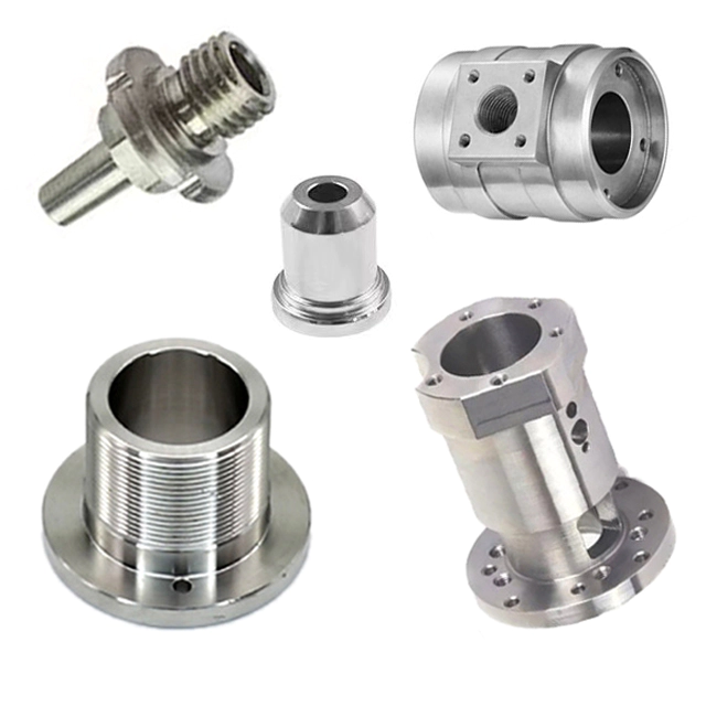

Discover the precision world of CNC machine parts: quality and endless possibilities
How to measure the roundness error in precision parts processing?
by:Jingte
2022-09-10
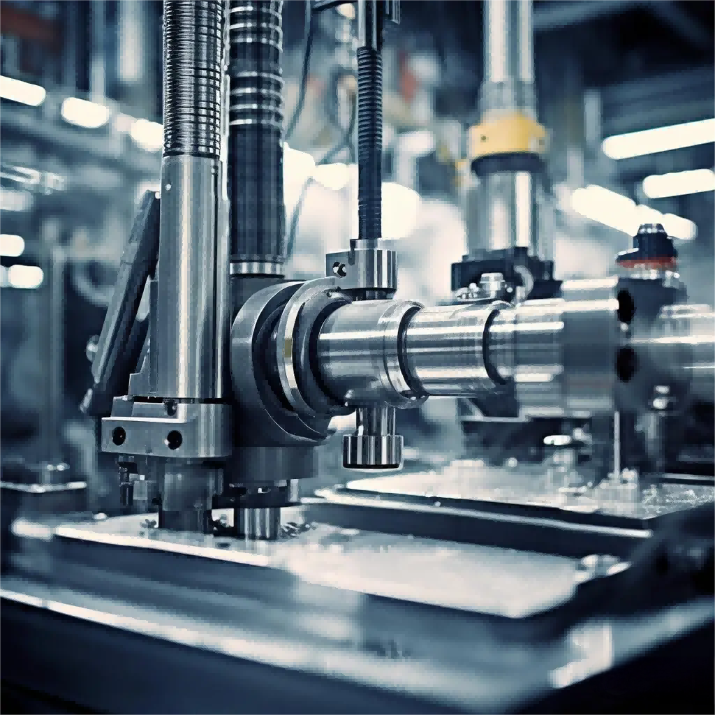
To check the roundness error in the machining of precision parts, the roundness meter method and the two-point method and the three-point method can be used. The rule of the roundness meter is to place the workpiece to be tested on the table of the roundness meter, align the axis of rotation, and make the probe of the roundness meter come into contact with the outer circle of the workpiece and rotate. Measurement results are displayed through sensors, amplifiers, filters, and calculation circuits.
If the output is the actual outline of the graph, the concentric circle template can be used to set the difference between the radii of the two inclusive concentric circles as the roundness error of a certain section. The roundness meter is suitable for measuring parts with high precision requirements.
Two-point method and three-point method When the shape of the measured contour is a circle with even edges, the two-point method can be used to measure the roundness error. Using measuring instruments such as calipers, micrometers, and micrometers, measure the maximum difference in diameter along the entire circumference of the truncated circle, and use half of it as the roundness error of the truncated circle. The calculation formula is:
Since the circles of the largest and smallest diameters are not necessarily concentric, this method is only an approximate measurement.
When the measured contour is a circle with odd edges, the roundness error cannot be measured by the two-point method, and the three-point method can be used at this time. The workpiece to be tested is supported by a V-shaped frame, and the maximum difference of one revolution of the workpiece is measured with an indicator, which is generally used as the roundness error of the section. Commonly used V-frame included angles α are 60°, 72°, 90°, 108° and 120°. The three-point method in precision parts processing can also be used for high-precision measurement.
Custom message
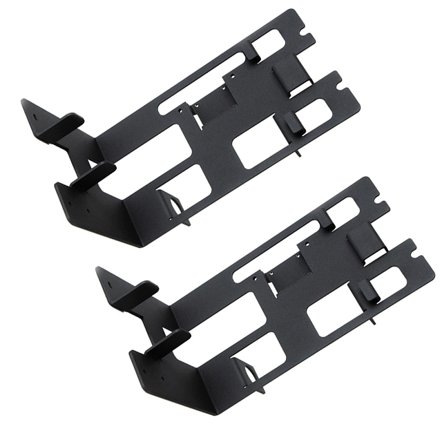
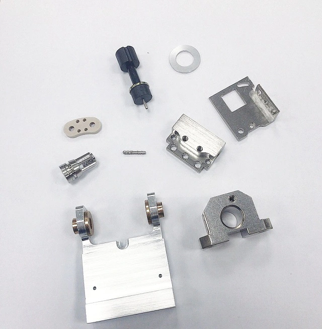
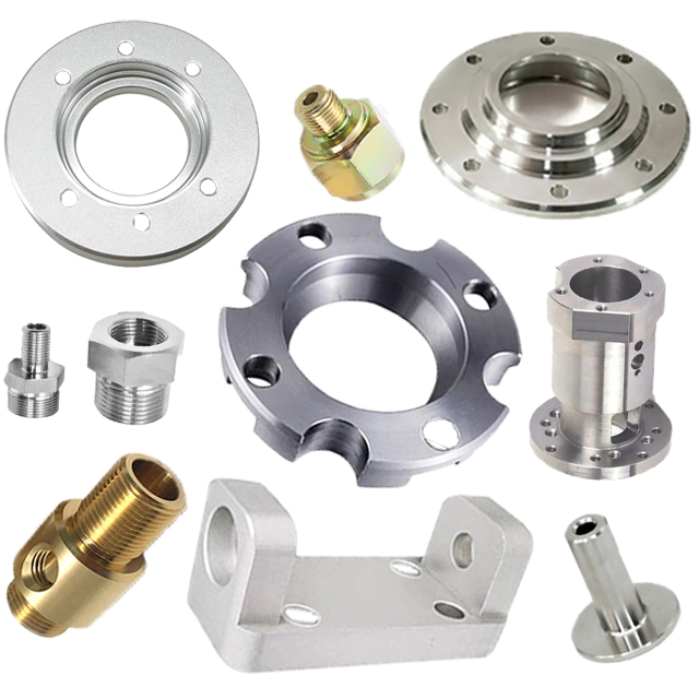
Related Products